Horizon S3 Pro Banding Fix
Shortly after I bought the S3 and started shooting with it, the dreaded banding issue started – first at 1/30th, then 1/15th. It finally reached the stage where going to the faster speeds didn’t get rid of it.
I set out to fix it and in the process nearly destroyed my camera. Unfortunately it’s not obvious to the novice as to how the camera works. What follows is a procedure for eliminating the fault, together with pitfalls to avoid.
The Short Version:
- Take the casings off the camera.
- Remove the brass clockwork speed control module.
- At the base of the lens turret, there is a gear wheel with two oval slots cut into it. There are two very soft rubber bushings there. Remove and replace these with tighter rubber bushings.
- Reassemble and go forth to a glorious banding-free future.
The Long Version:
Set a clean, fluff-free towel down on the working area. Get decent lights set up.
Tools: jeweller’s screwdrivers, tweezers or fine pliers, long nosed pliers with linear serrations on the jaws, parallel points optical spanner or very fine circlip pliers. The Allen keys are there because I’d changed some screws.
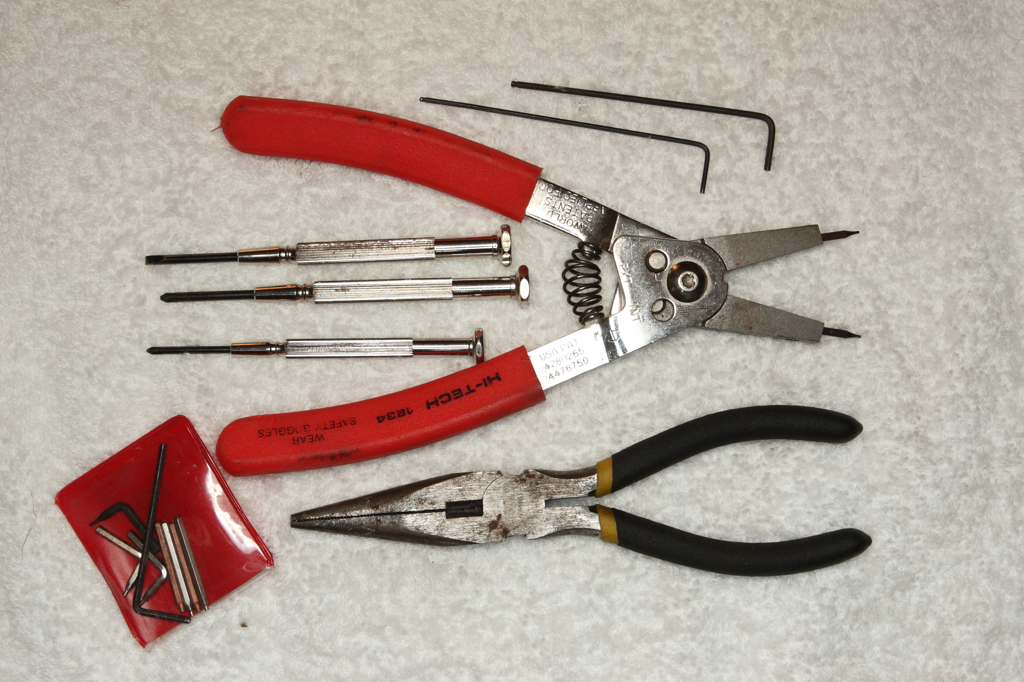
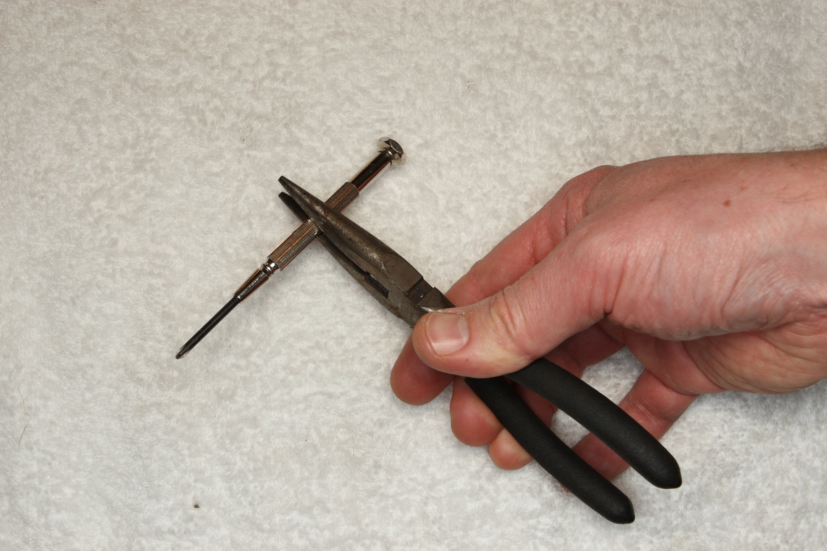
If a screw needs torque to undo, a useful technique is to steady the base of the screwdriver and apply torque via the serrations on the screwdriver body and the jaws of the pliers.
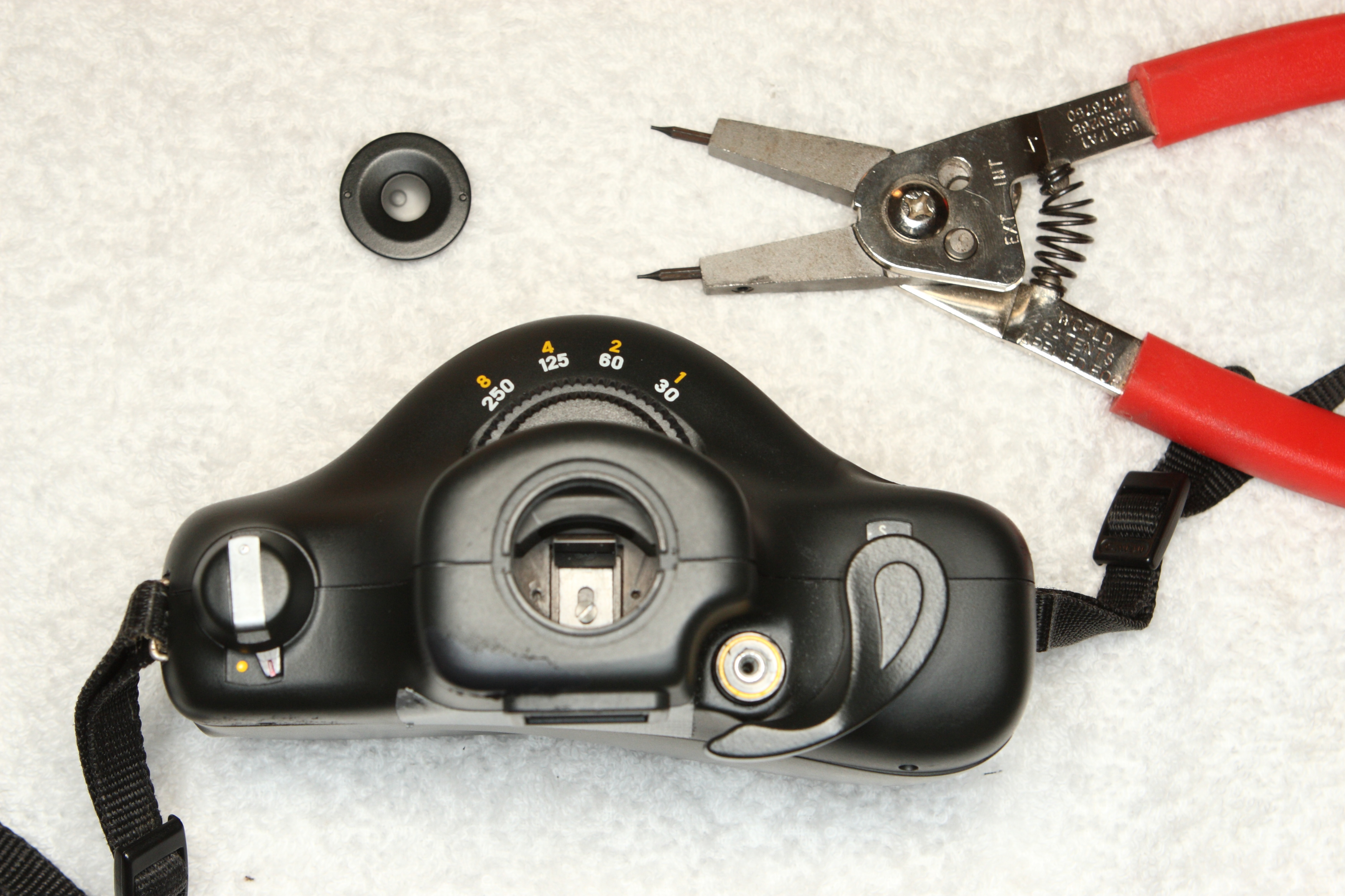
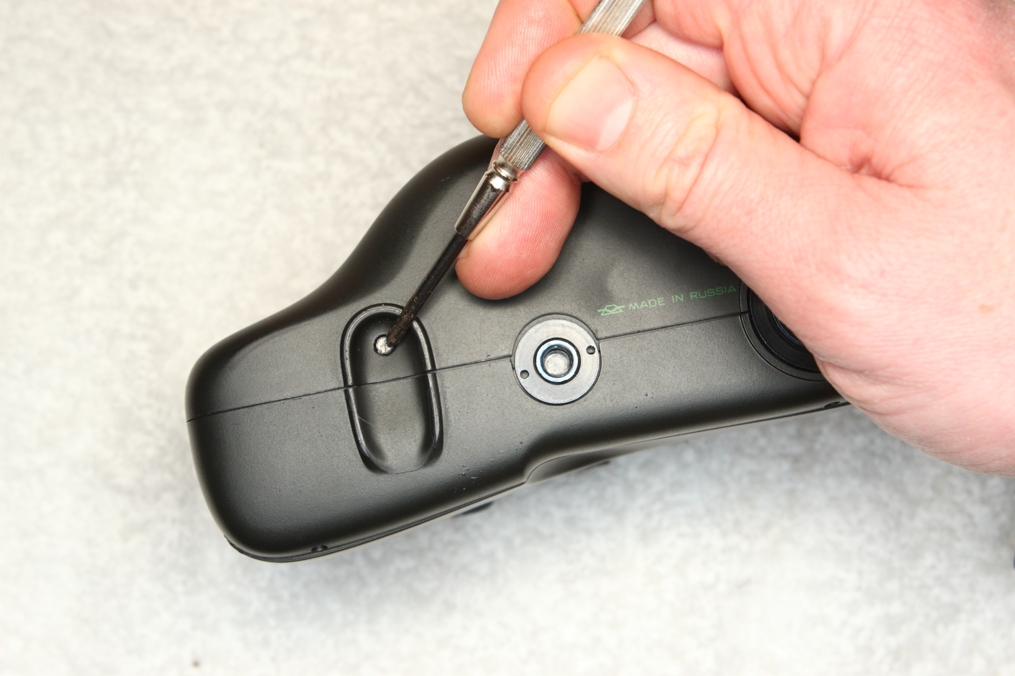
Set the camera on its base. Use the optical spanner or circlip pliers to unscrew the bubble level in the top of the casing. Remove and set aside.
Set the camera on its back. Unscrew the two phillips screws holding the front of the casing in place. Fully depress the film rewind button in the camera base, using a screwdriver to latch this under the casing. Pull the front casing half off, and then remove the pins for the neck strap and remove this as well. Set the film rewind’s plastic plunger somewhere safe – it is easy to drop and lose this.
Set the camera on its face. The plastic cover for the film advance lever is held on by a single screw underneath, at the lever tip. Unscrew this, remove the plastic cover, set the cover aside with the screw. No matter how tempting it is, or practical it looks, do not attempt to unscrew the metal film advance lever from the film advance shaft. The screw holding it on will break rather than come out.
Remove the four phillips screws holding the back casing on.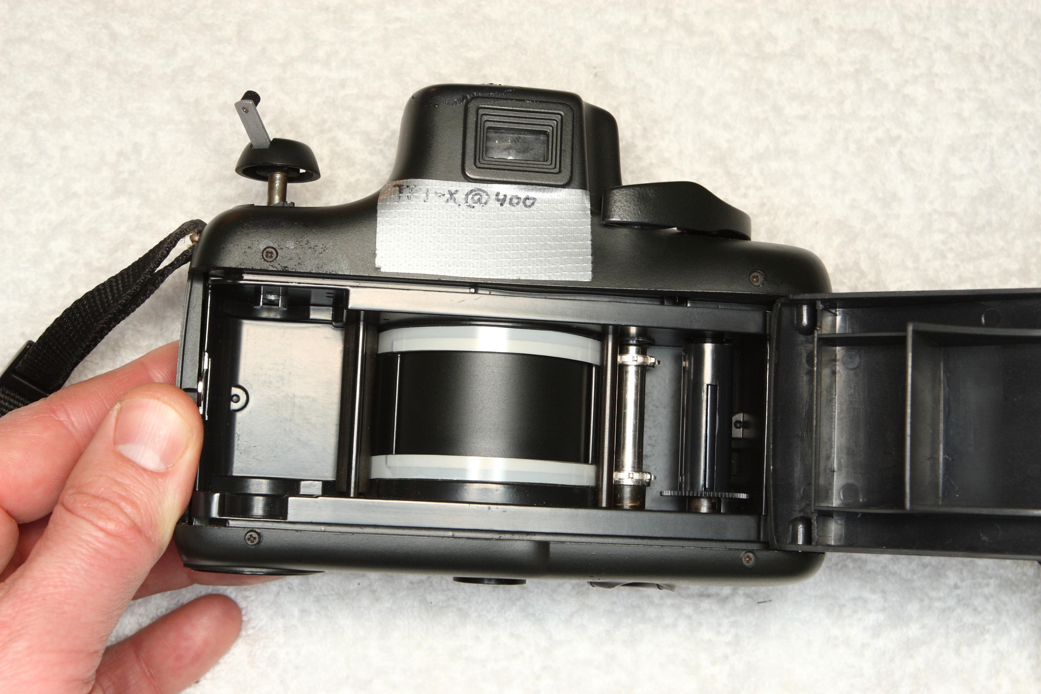
Use the circlip pliers or optical spanner to remove the normal tripod mount and the handgrip mount. Now here’s where it gets tricky…
Release the film door latch, by pulling the rewind lever up. Holding the camera upside down, move the casing a little outward from the back base, leaving it in place at the camera top. Using a screwdriver to flex the plates holding the film door hinge pins, release the film door. These plates are black, inside a black casing, tucked into a corner. You may have to get right into the corner with a penlight to see them, but they are accessible.
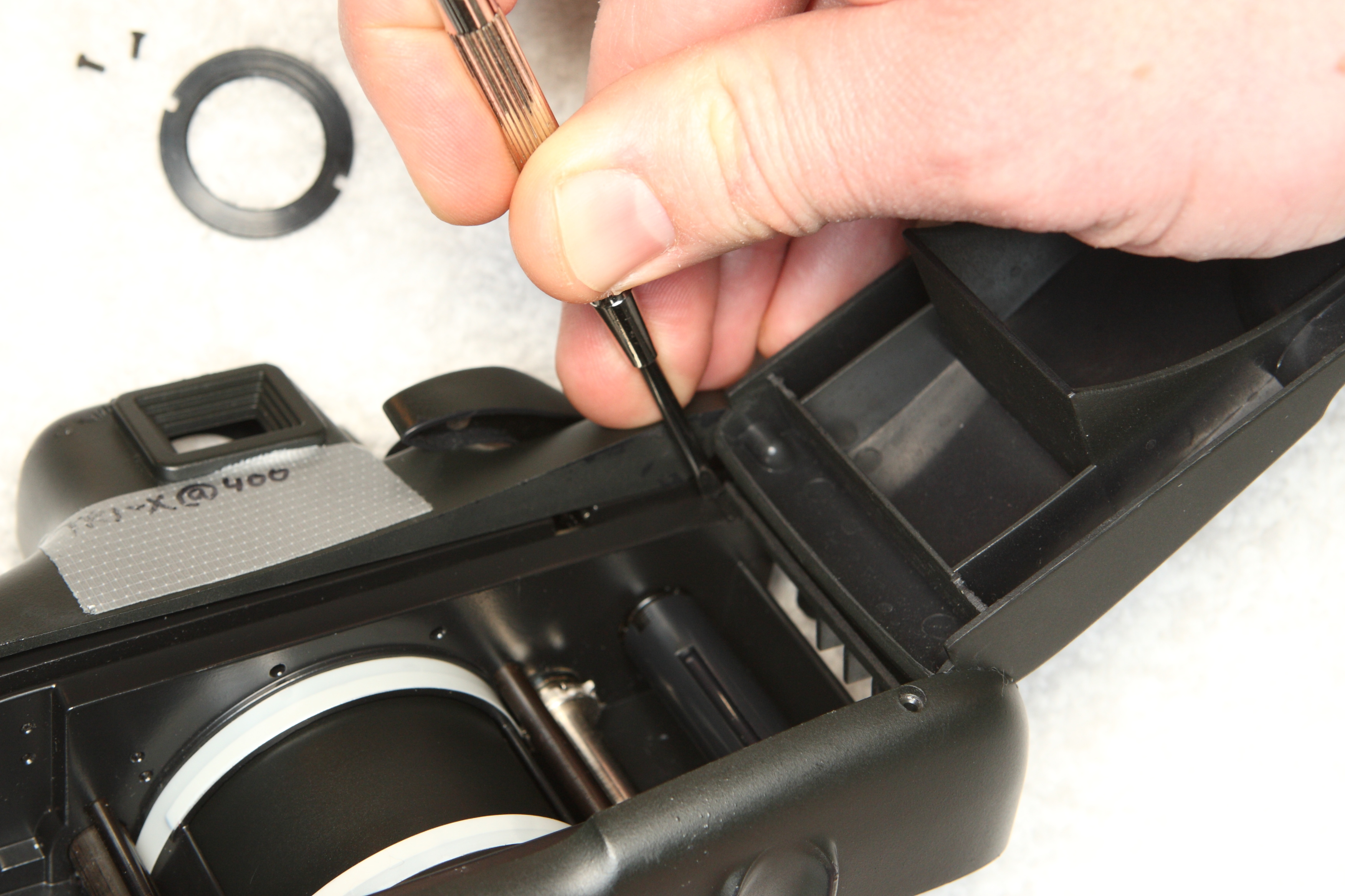
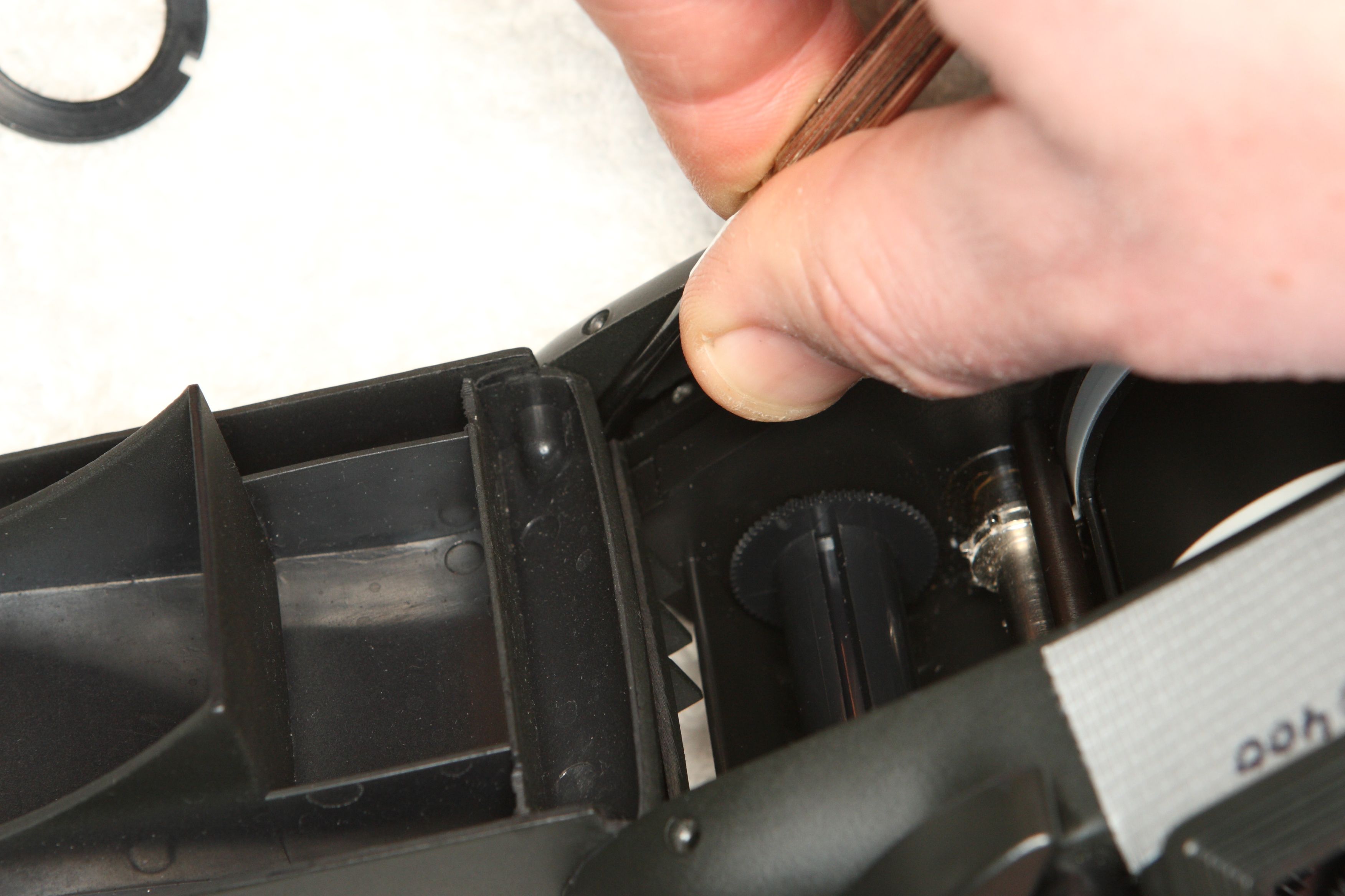
Pulling the back case outward from the left of the camera, see if you can work the film door free. Don’t be shy about flexing the case a little, the plastic can handle a reasonable amount of force. I removed mine by taking the door hinges to the middle of the opening, slightly twisting the film door, and popping the hinges out that way. Note that there’s nothing holding the hinge pins in place on the door itself and these can easily drop and be lost. Keep the door above the towel at all times so if they do drop, they don’t go far.
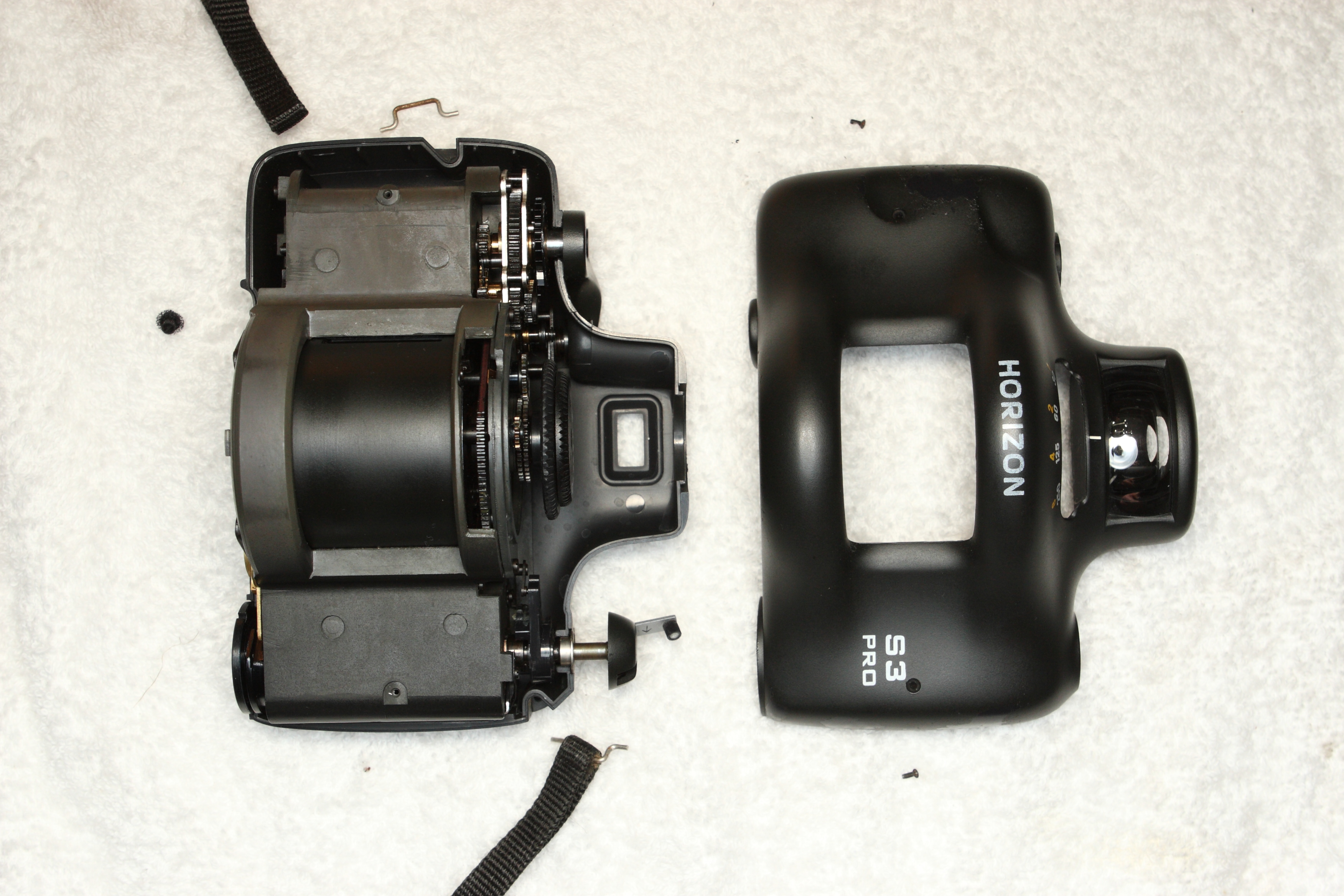
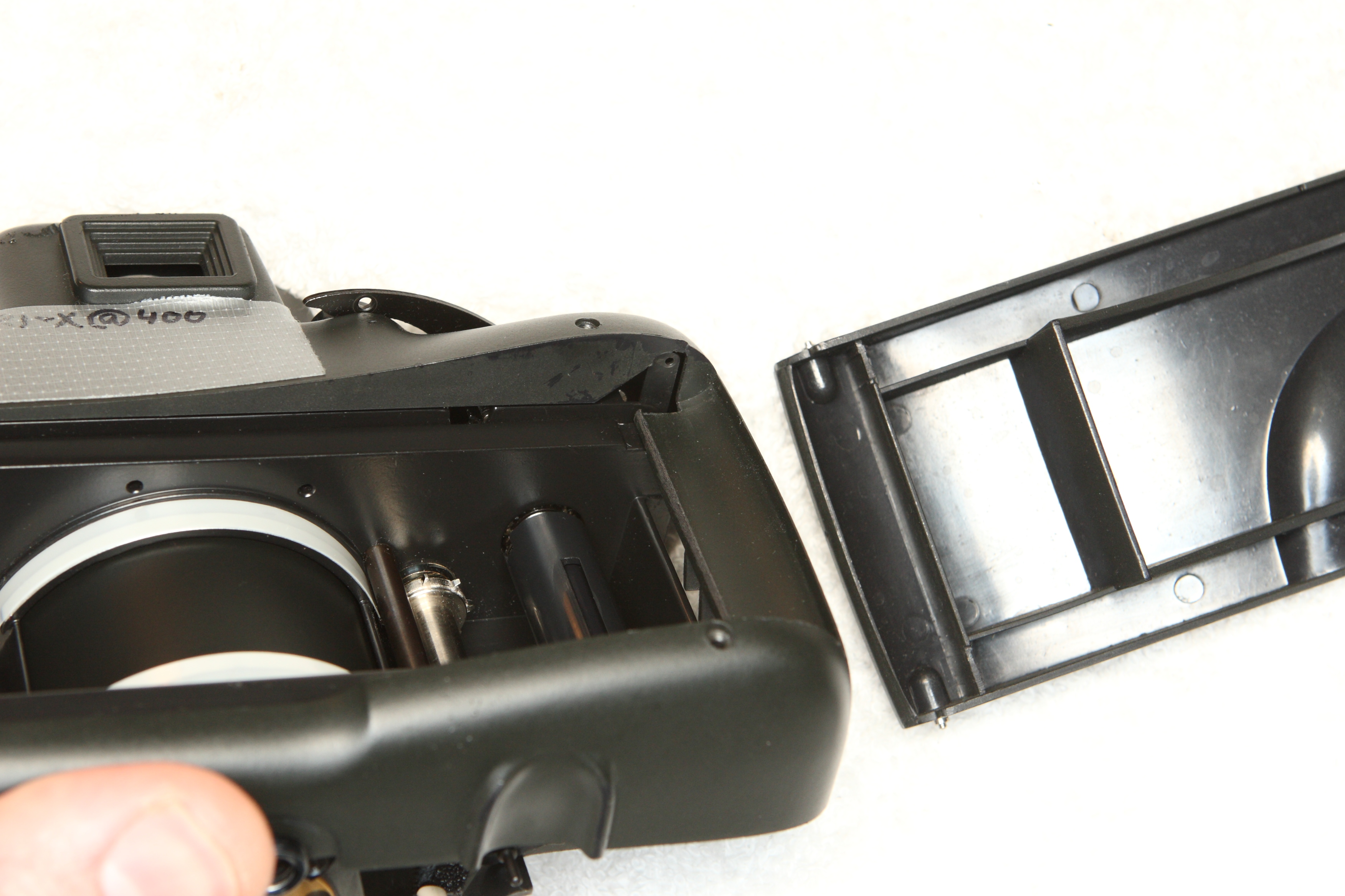
You don’t have to fully remove the back casing (this is very tricky to do and involves flexing the plastic around the shutter release button rather hard). It’s possible to push the casing back and out of the way:
You don’t have to remove the handgrip mount, but it does make life easier with removing the speed governor module.
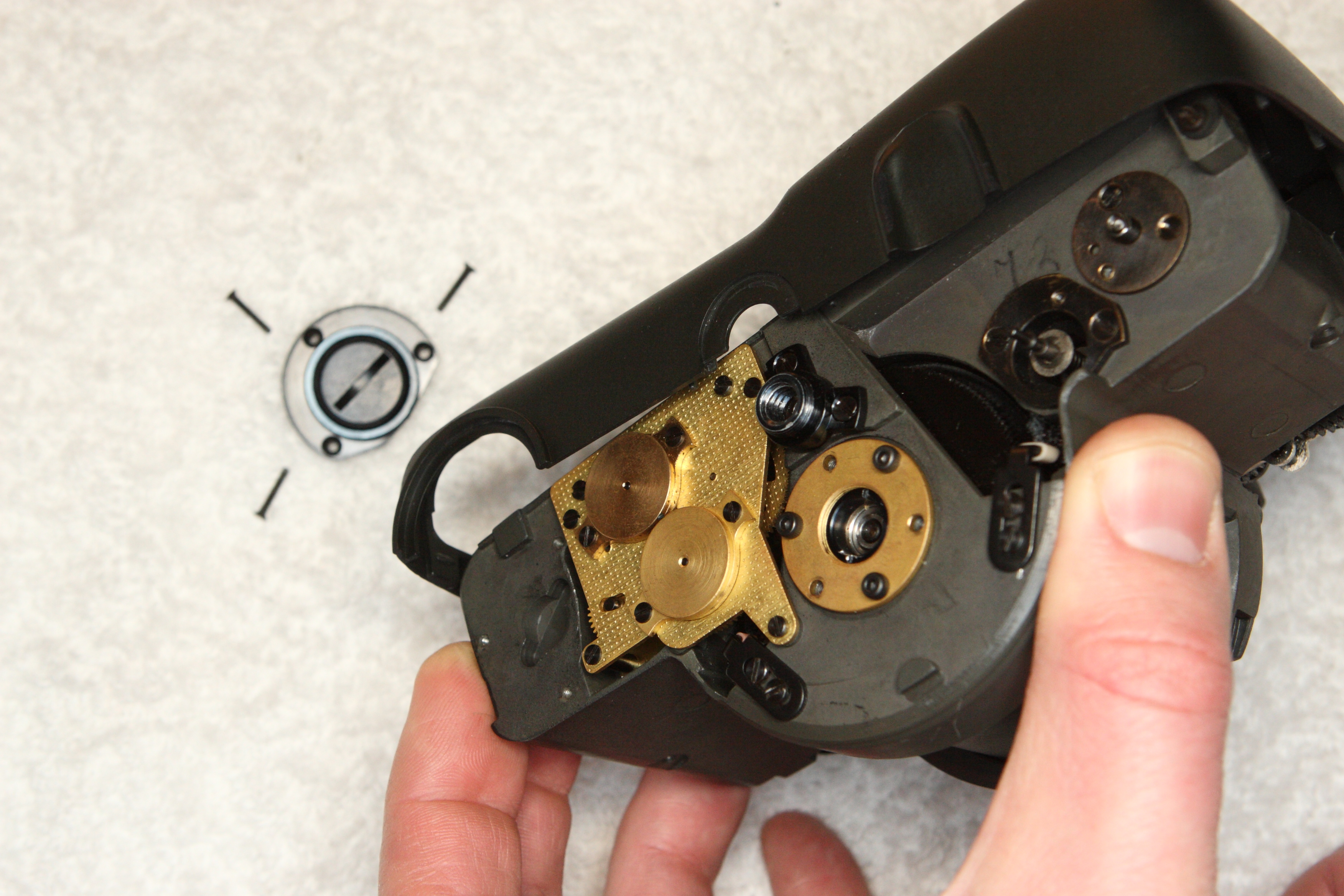
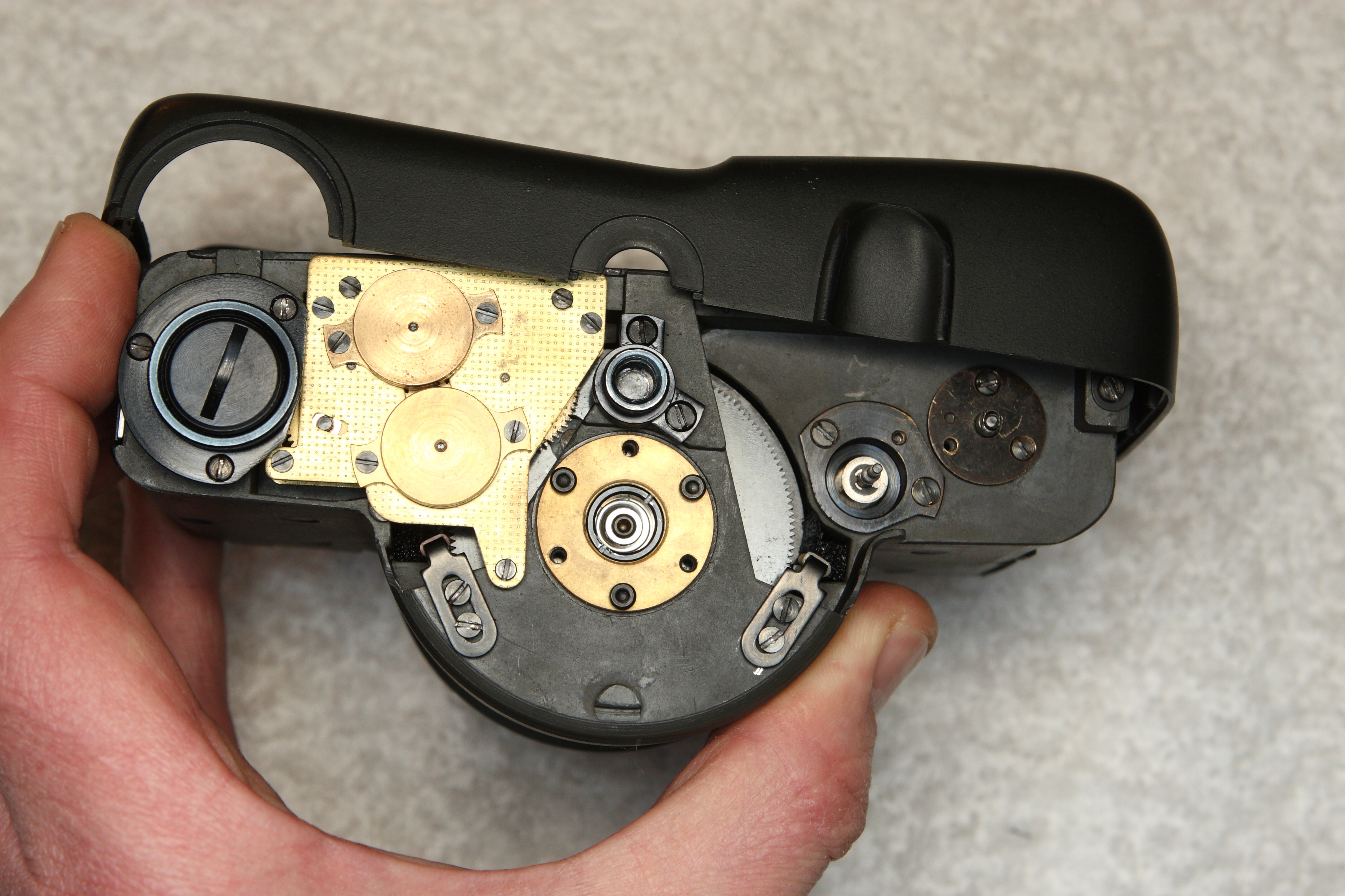
Take care to avoid screws holding the two brass plates together. Unscrew the three mounting screws only and then remove the brass assembly. This module is the mechanical speed regulator for the camera, using two centrifugal brakes to control the turret’s rotational speed. One of these brakes is on an additional pair of spur gears and can be switched in and out, in order to provide the slow set of shutter speeds.
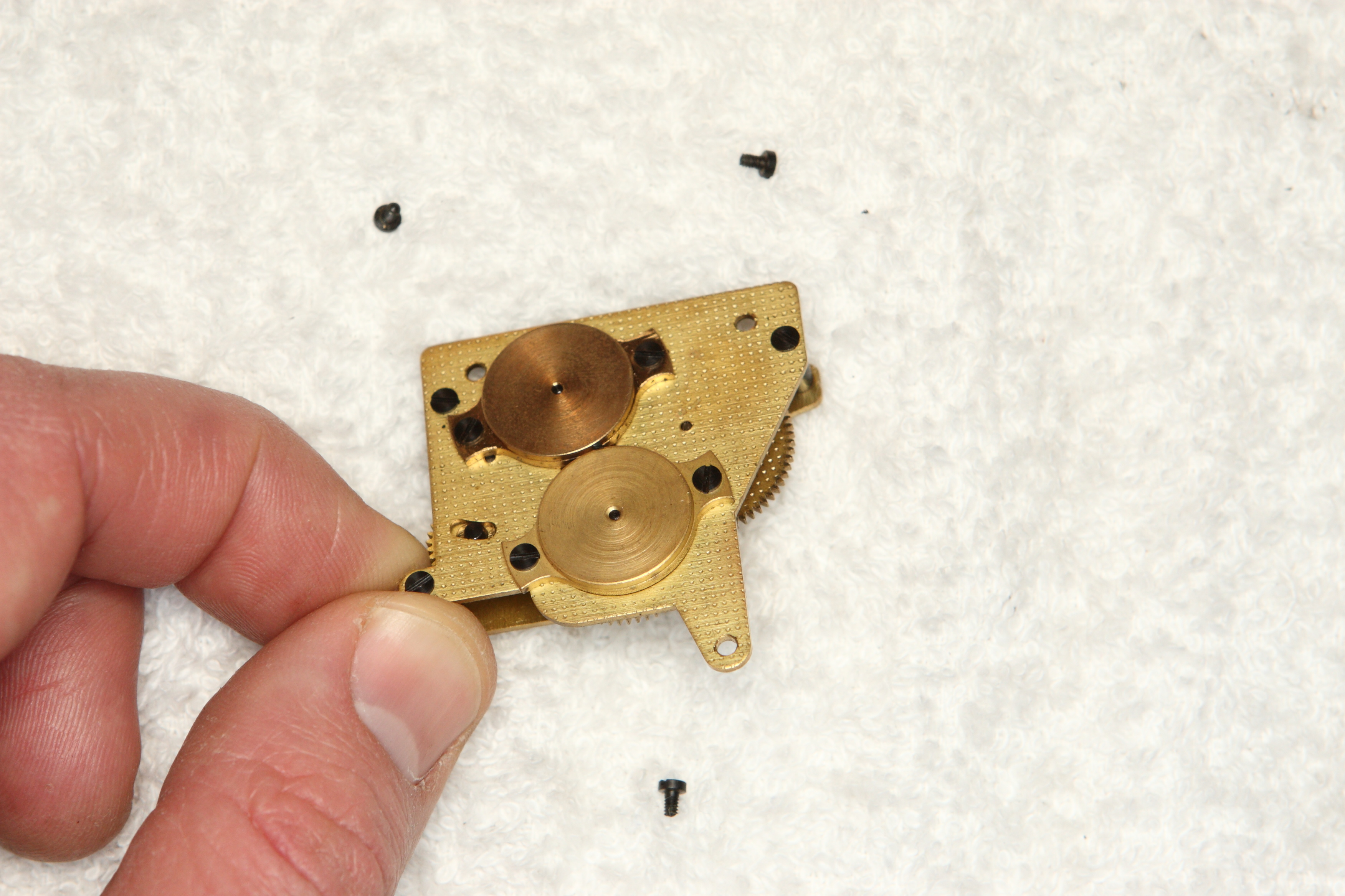
There may be some oil present. This is normal – the banding fault is not caused by this module, unless there is clearly damage or dirt present.
Do not attempt to dismantle or remove:
The two plastic dials at the top of the turret for shutter speed and aperture. You don’t need to touch this assembly, and again, the narrow fastener holding these on appears to be locked on.
The film winding mechanism, including the wind-on lever on top and the lever stop at the camera base. The two screws at each end of the main shaft are effectively locked into place and will break just under their heads rather than come out. Break either of them and you’ve effectively ruined the camera.
The film winding mechanism itself. If for any reason the camera isn’t winding on far enough, or won’t release after winding on, suspect the little folded timing trips on top of the turret first.
The timing trips on top of the lens turret. These are not at all obvious as to what goes where – there aren’t outlines marked, or numbers stamped, or any guides to help with putting them back on. If you for any reason take these off, take photos before, during and after.
The centrifugal braking mechanism. If in doubt about oil or dirt, washing via solvent in an ultrasonic bath or by repeated immersion and running gears while assembled is the way to go. Allow to dry and relubricate with watch oil before refitting.
The round brass disc with six screw holes, held in place by three screws, at the base center of the turret. There is a bearing visible in its center. This tensions the helical spring which drives the camera, and unscrewing this will allow this spring to unwind, thus turning this brass disc at high speed. It’s then a matter of guesswork trying to figure out how many turns to put on it, and searching your entire lounge for the last remaining tiny black screw that it has slung out when it released. Like I said, pitfalls for the unwary.
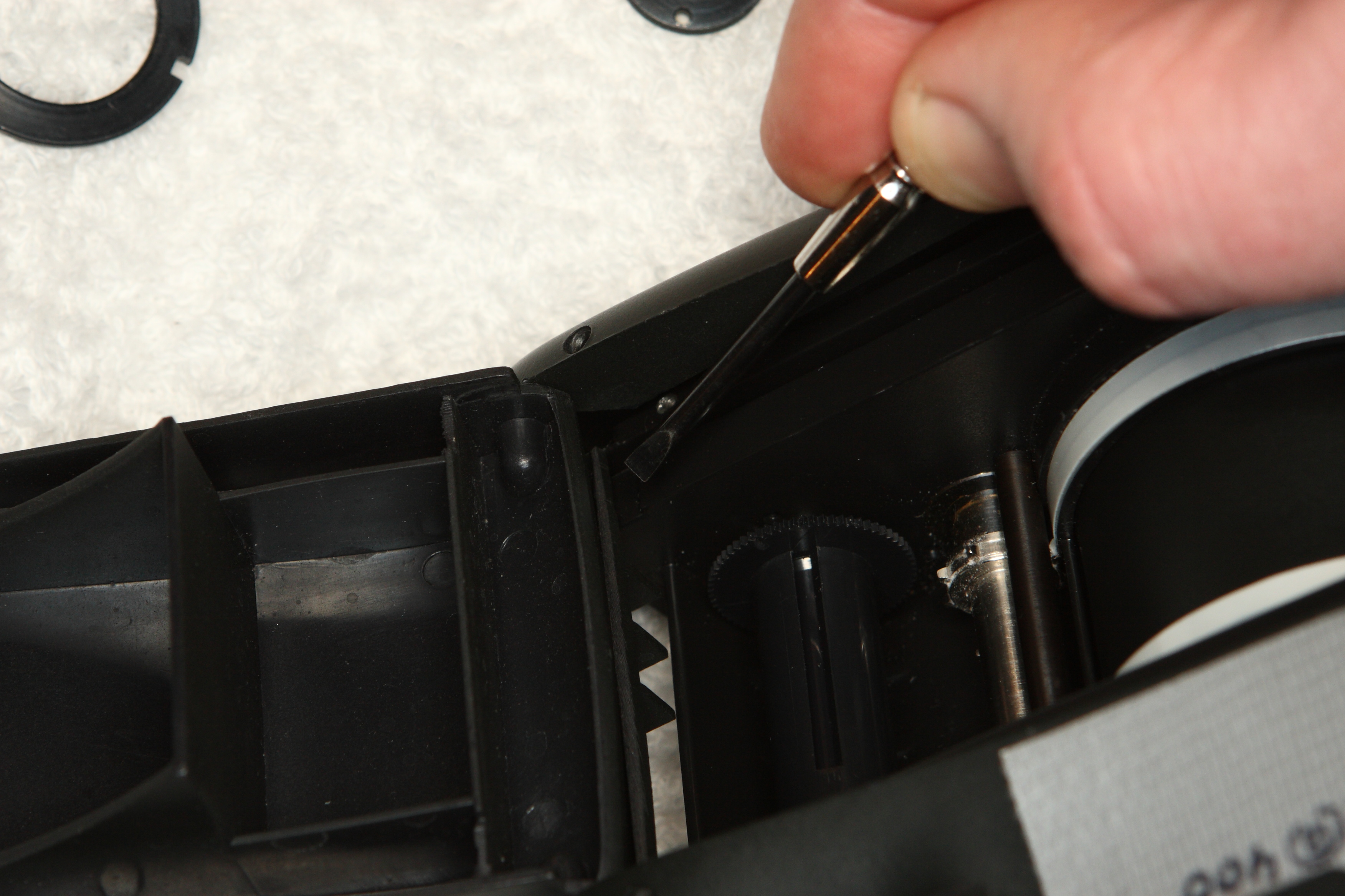
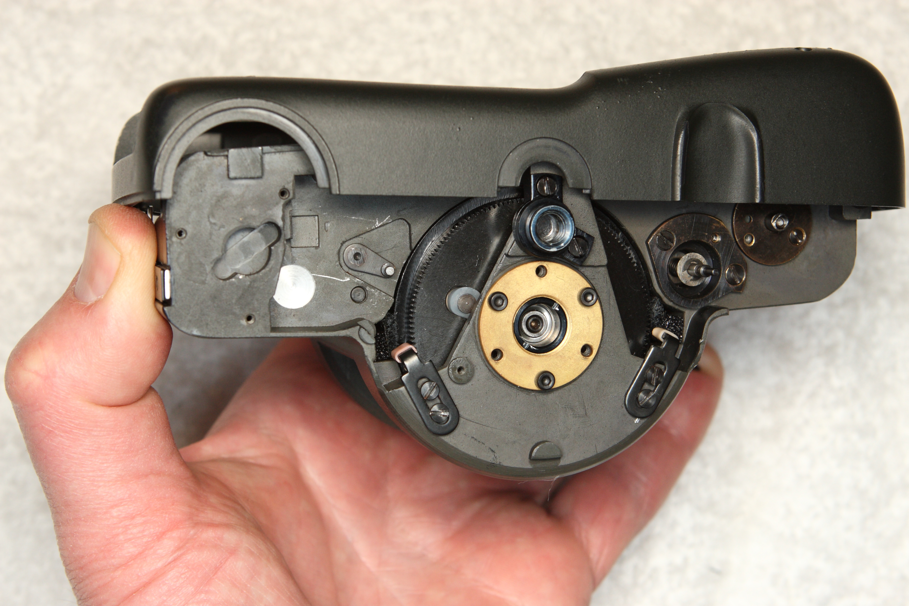
And now to the good bit… here’s where the banding fault is located. There’s a gear wheel visible at the base of the lens turret. It’ll only be accessible once the centrifugal braking module is removed. This gear wheel has two oval slots cut into it, one on each side. There is a driving pin in each slot, cushioned against shock by a cylindrical rubber bushing.
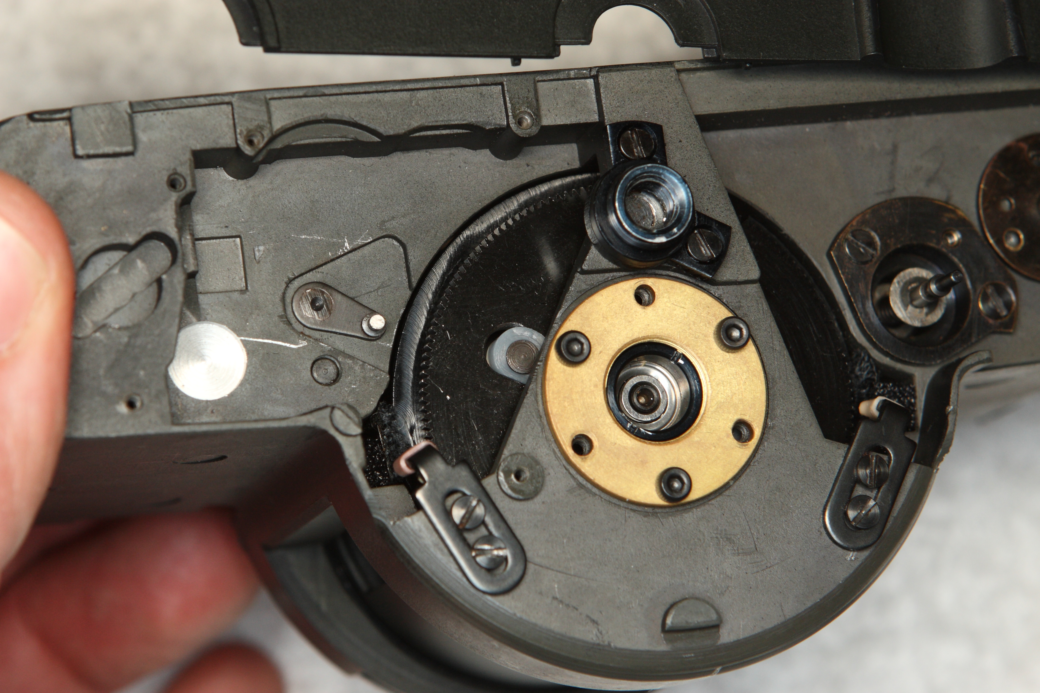
The bushing in this photo has already been replaced – this is the white element beside and just under the round brass disc. The rubber bushings are small and soft enough to permit torsional vibration of the turret against the centrifugal clockwork brakes during exposure, and this is where the banding problem comes from.
Using tweezers and a fine screwdriver, pull the near side of the rubber bushing up, then draw the entire bushing out.
Cut a new bushing from appropriate sheet rubber stock, or rubber tube. Dimensions are: Pin diameter 2.8 mm, outer diameter 5.2 to 6 mm (depending on how hard the rubber is, and how much you want to reduce the turret bounce), length 3mm. I tried fitting some white silicon rubber, cut from tubing, with a 6mm OD.
Somehow get these new bushings over the turret drive pins and stuffed into place in the gear wheel’s slots. Working the gear wheel up and down will help with this. There are two bushings, set 180 degrees apart. You will have to wind on to get at the second one. Take care if you release the shutter, the turret will swing at considerable speed and then stop with a bang. Control the turret’s motion by holding it.
Re-fit the centrifugal brake module and take the chance to test the camera. Note that the gear selector should be on the faster shutter speeds when you do this (select at camera top).
Shutter Speeds: A quick way to test the shutter speeds is to look at the time needed for the turret to rotate on the slower gears – this time should be roughly 9.2 seconds. If it’s running slowly, clean and lubricate the centrifugal gear mechanism, or increase tension on the main turret spring. This is done by (carefully) removing two of the three screws holding the central brass disc at the base of the turret, then loosening – not removing – the third. This will let you feel the tension, its direction, and its strength. Holding the brass disc still, remove the last screw, change tension as suitable, refasten the plate.
Shutter Release: this can become intermittent or even jam if the little timing trips on the top of the camera aren’t making proper contact with the right parts of the winding/release mechanism. The fix for this, perversely, is at the base of the camera. There’s a hollow nut fastener, apparently holding the turret bearing in. This seems to set the turret height, but it isn’t locked in place by anything, and it may have worked its way loose and unscrewed. If this happens, the turret will sit low, the trips won’t work properly, and the camera may develop an incredibly annoying problem with locking up after being wound on. I’d suggest using a low-strength threadlock if this has happened.
Shutter Curtains: There’s a pair of brass spring-plate trips on the turret top which adjust these, together with their respective timing trips. Their purpose is to make sure that the shutter curtains are closed in one direction, open in the other. A few open exposures should confirm that these are working properly, if not, adjust as suitable.
Check and clean the gears. The gears at the top of the camera are for winding on, and are meant to run freely during an exposure. They can affect shutter speeds if there’s grit caught in their teeth, though. The gear train at the camera base controls turret rotational speed and therefore exposure, via speed up spur gear pairs and centrifugal braking. If you’re having single or irregular bands on exposures (at all speeds), then give these gears a thorough clean (I’d suggest with a new toothbrush) and relubrication. Note that these bands will happen in the same place repeatedly if it’s a problem with the top gearing, but may move around or appear / disappear if it’s a problem with the base gearing.
Reassemble the camera. If you’ve got this far, then this shouldn’t be a big deal. I found that I had to fit the film door after the rear case of the camera, but otherwise, it was done by reversing the sequence above. Be sure that the front casing is edge-matched properly to the rear casing – this is a tight fit and may need careful pressing to get it to click into place. This has to be done before the front casing screws can be properly fastened home.
Done! Time to go shooting.
